- Serial cable
- A computer capable of running Terminal software. It can be any OS. A laptop is preferred (I’ll call this the configurator)
- A network cable cat5e or better preferably
- Terminal software. I use TeraTerm. You can use any terminal software that supports VT100 serial connection like Hyper Terminal.
I. CABLING
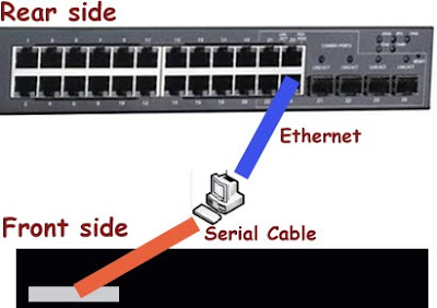
With your switch powered off make the following connection:
- Connect your computer(configurator) to your switch using the serial cable
- Connect your configurator to your switch using an ethernet cable. Plug the ethernet cable to the last port of your switch. This is to help you configure the switch with the GUI, without having to know all the command line. I chose to use the last port of the switch because this is the port I won’t configure.
Your configuration should look like this.
II. CONNECTING WITH SERIAL CABLE
Run your terminal software in VT100 mode, and configure it with the following setting so that you can connect to your switch:
- Port: Whatever your COM port is for your serial connection
- Baud Rate: 9600
- Data: 8Bit
- Parity: None
- Stop: 1 bit
- Flow Control None
III. INITIAL SETUP
After the above is done, turn on your switch, and establish the serial connection with the above setting. Hit enter one or more times. You should see the POST message from the switch on your terminal screen. If this is not the case, check your connection and settings above. You cannot go any further without having this step completed.
After it’s done booting, it will prompt you for a easy setup. it will timeout after 60 seconds(if I’m not mistaken). If it does time out and you miss it, turn off the switch and turn it back on again(you can also type reload to reboot the switch). Follow the instruction of the easy setup. Keep the following in mind:
- If you are not configuring SNMP, type “no” when prompted
- It will ask you for IP address and subnet. For simplicity sake, I’m using class C IP address: 197.167.1.1 and subnet 255.255.255.0
- Don’t worry about the default gateway. You can type in 0.0.0.0 as the IP for the default gateway.
- at the end of the easy setup it will prompt you whether you want to copy the running configuration to startup configuration. Type Yes only if you have entered everything correctly. If you need to make correction, type no, and the easy setup will re-run. If you get the IP address and the subnet right, don’t worry about others. You can make changes from the web interface later. After you make configuration changes, if you want it to stay after the switch reboot, you need to copy your running configuration to your startup configuration(shown later).
IV. GETTING READY TO UPDATE FIRMWARE
After the quick setup is finished, you need to upgrade the firmware of your switch. Make sure you download the latest firmware required from DELL’s website and save the file on the configurator before you proceed any further. As of this writing, the latest firmware version is: 2.0.0.41, A06. If you have a laptop with both ethernet and wireless card as your configurator, life will be easier because you can use the ethernet connection to talk with the switch, and the wireless to connect to the internet to download the firmware.
The easiest way for me was to upgrade the firmware using the GUI provided by the embedded web server of the switch. To accomplish this, you need to connect to the switch using ethernet connection. Make sure your ethernet cable is plugged in to both the configurator and the switch. Change the IP settings of the configurator(the ethernet connection that plugs into the switch) to the following:
- IP address: 197.167.1.100 (this can be any IP from 197.167.1.2 to 197.167.1.254)
- subnet: 255.255.255.0
- Default gateway: this has to be the IP address you provided during the easy setup. In this case, it is 197.167.1.1
Fire up your browser, and type in the switch’s IP, http://197.167.1.1. You should be prompted to login. If the browser is not displaying anything, double check the configuration above, and do not proceed any further(oh well, you can’ t anyway. Unless you know all the command line). Login using the credential you provided
After you login, do the following:
- using the navigational tree on the left, click through the following: File Management > File Download > Firmware Download > Download via HTTP.
- Click Browse, and select a file with ROS extension from extracted firmware you just downloaded from DELL.
- Select “software image” as the “server type”, select “image 2” for “Active Image After Reset” field
- Click on apply changes
- After the download is done(this is actually the transfer of the firmware from the configurator to the switch. The term is confusing), reboot the browser by clicking through the following: System > General > Reset >Reset. Click okay twice. The word “Reset” is somewhat misleading. It should be renamed to reboot, or reload. This reset will not wipe out the changes you made. It will simply reload the browser.
- To reboot your switch from the terminal console, make sure the command prompt ends with # instead of >. if it ends with >(i.e console>), type “enable” followed by enter, and then “reload”.
- hit Y when prompted. this will reset the switch
Now you need to check whether the firmware is loaded up fine. Bring up your terminal window, and wait until the switch is done rebooting. Hit enter key. If it’s done booting, the console will display “your_switch_name>” prompt. Type “enable” and enter. The switch console should turns to # after you enable it. Type in “show bootvar “. This should show the latest firmware version(should be the same version as the one on Dell’s website). As of today, the latest firmware is 2.0.0.41.
- For action item #2, select a file with RFB extension from the extracted firmware you downloaded from DELL’s website.
- Change the “server type” in action item #3 above to “boot code”.

Let’s configure it.
#end configuration
After the switch reboot itself, your configuration should stay intact.
- Change something from the web interface, like time zone
- You’d like to see what the value of your encrypted password is(so you don’t have to enter your password in clear text in configuration file, which I’m sure you’d like to store somewhere)
Then do this:
- From your web interface click through the following: System > File Management > File Upload.
- Click on “Upload via HTTP” option
- Change the “transfer File Name” option accordingly. Running configuration is your current configuration after whatever changes you did. Startup configuration is what the switch will use the next time the switch is rebooted. Every changes you made on the web interface or terminal console will be saved to Running Configuration. You will need to manually copy to startup configuration. Otherwise, the changes won’t apply when the switch is rebooted.
- Click apply changes. This will download either the Running/Startup configuration from the switch to the configurator.
- You can open the text file with notepad, and see how it’s done.

What are recommended switch options that should be configured for the iSCSI SAN? Thank you.
it really depends on what you require. some switch has a lot of feature/security feature built in. if you will be using the switch mainly for iSCSI, all you need to look at is whether a switch supports configuration i mentioned in the article. not necessarily one that comes with all the bells and whistles. I chose dell switch because it’s more cost effective compared to cisco switch. this article might help.
Excellent Article
Hi, I love your site http://digitallibraryworld.com but when I make a comment I get a 403 error on occassion. Thought you may want to know
thank you!! that 403 is because this IXWEBHOSTING company is a very UNRELIABLE web hosting company. i just haven’t had time to research what’s good out there.
Great stuff mate. Thanks a lot
Hi,
Thanks for the intuitive post, it was very useful for getting our MD3200i array configured with two Dell 5424 switches (not stacked) and three R710 hosts. Each esxi host has 4 broadcom nics dedicated to iSCSI traffic, 4 intel ports for vm machine network traffic, 2 intel ports for management, 2 for FT/vmotion.
questions that you might be able to answer.
1. Are your path selection set to MRU or RR?
2. Storage Array Type: by default it’s VMW_SATP_LSI, can this be changed to VMW_SATP_DEFAULT_AA or is that not supported?
3. On the MD array, the segment size is 128K for Virtual Disks, is this the correct segment size for VMFS? Do you suggest changing it to something else?
4. By default VMFS (ESXi 4.1) is set to 64K. Should this be changed?
5. Do you know any references to the correct BIOS settings for vmware for the R710 or the poweredges? I’ve looked everywhere and can’t find it. I know VT should be enabled but that’s about it.
6. Any other information that you can share would greatly be appreciated.
Thanks.
Hmm, i’m not using VMware with this switch. I’m using HyperV. so i don’t think i can answer any of your question. this post might help though.
http://en.community.dell.com/support-forums/storage/f/1216/p/19347417/19753827.aspx
I also remember seeing a best practice documentation on Dell website for VMWARE with md3220i. You might want to check that out. I believe the link was in the product description page of md3200
Yes, thanks. This is how I have my iSCSI network setup currently, Using my implementation of VLAN 2 and 5 for multipath traffic.
I’m not sure if we will be implementing Failover clustering at all with our systems… but the extra VLANs aren’t hurting anything by being there.
Thanks for the clarification, I look forward to reading future articles!
Great article, it really helped me out a lot!
One part has me confused and I haven’t been able to find clear answers about it…
Can you explain the failover process and configuration with the separate VLANs? In your example you have VLAN 2 and 3 on switch 1 and VLAN 5 and 6 on switch 2. In production, only VLANs 2 and 5 are being used. In the event of emergency or disaster, what happens? Say for example, switch 2 fails. I would move the cables from VLAN 5 over to VLAN 3 on switch 1. But since it is configured as a completely different subnet, I would then have to go through all my servers and the MD Storage manager to update everything to the new VLAN ID.
To me it makes more sense to have Switch 1 set up with VLAN 2 and 3, and then Switch 2 set up with VLAN 3 and 2 in that order. So moving the cables would be all that is necessary to bypass a busted switch, no reconfiguring of VLAN IDs anywhere…
Am I missing something??? Thanks!
i think i am confusing you with the term failover. The vlan i setup for failover, is intended for Windows Failover Clustering, NOT for iSCSI data traffic.
each Vlan(2 and 5) has DUAL PATH traffic, one is going to a port in CONTROLLER0, and the other is going to a port in CONTROLLER1. You also configure your MD3000i with 2 VLANs, VLAN 2 and 5. look at the last image above for reference. Pay attention to the color coding, and see what happens when switch 2 fails.
If switch 2 FAILS, that means VLAN 5 is no longer accessible(the green path died), but data can STILL access the md3000i through VLAN 2- the gray path(assuming your server has dual NIC card, one is configured with VLAN2 and the other is with VLAN5). You don’t need to switch cable and reconfigure your md3000i, it will do it automatically for you. But in order for this redundancy to work when a switch completely dies, you do need to configure your iSCSI connection on your host server with RoundRobin with subset. I haven’t had time to write documentation for this yet.
hpe that helps
That is not true, if you configure Round-Robin correctly on each LUN, ESX will switch the path to the other switch. I did not link this setup, I set mine with 2 vlans one for LAN and one for iSCSI. That it’s all what you need. No need for cable switching or any of that crap at switch hardware failure. you don’t need that, this is what multi-pathing is used for.
jesbuddy07 is correct with his reply.
I have two PowerConnect 5424's and an MD3200i. I too got lost in the gap between Dell best practices (hard to find) and what the guides say. This is a VERY helpful how-to.
to anonymous' comment on August 31, 2010:
go to the product site for md3000i, i remember seeing a best practice guidelines for vmware environment. I pretty much follow the one for iSCSI using HyperV. It should be similar but don't quote me.
to anonymous' comment on august 30:
You need to try several port type. There are 4. general, access, customer, trunk. I'm suspecting you need either the general or the access. the best way to test this is probably trying to configure one or two ports using the web interface first, then save it to running config, then see the command line for those configuration. I explained the steps to accomplish this under on my post under "If you'd like to see the command line when you do the following:". To allow all packet(both tag and untag), on the web interface, you can go to: Switch, VLAN, Port Settings, and under Frame type change Admit All.
To make a port become an untagged vlan, set it to the default vlan 1. This can be done in switch, vlan, port settings.
You can also go to Switch, VLAN, Vlan membership. The table at the bottom shows the status of each port (T= tagged, u = untagged). You can click on the T or U to change the status.
There is user guide for the switch titled "Dell™ PowerConnect™ 54xx Systems User Guide". You can probably find this on the DELL site(under resources CD i believe)
what is the suggested configuration for n.2 hosts (dell 710 with 8 pNIC)running esxi 4.1, n.2 switches 5424 and an MD3000i?
I would like to use the switches for iscsi and possibly vmotion traffic at least and an optional small vlan for the management will be also appreciated if possible… Thanks
Great stuff, I'm about to hook up a similar setup, but I'm using a EMC AX4-5 SAN.
I belive it dosn't support VLAN tagging, do you know how I should setup the ports to allow non-tagged packets? Can I just remove these two lines, or should I add another configuration.
switchport general allowed vlan add 2 tagged
switchport general acceptable-frame-type tagged-only
In the manual it says:
Even though VLAN tagging is not supported if received by the storage system's iSCSI ports, Ethernet switch-based VLANs are supported.
This is really useful! I saw your post in Dell Tech Center and having the same problem setting up my PC5448 with PS6000XV. My email is chi****dio@gmail.com, pls feel free to contact me. Thanks again!